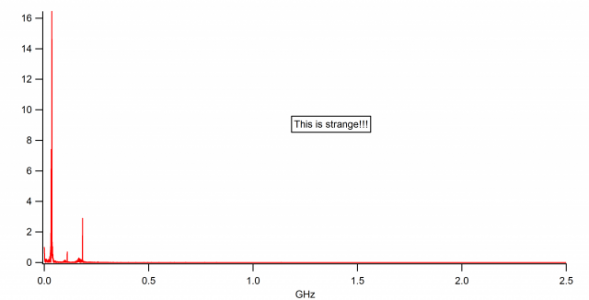
FFT transformation of the magnetization change in time
I am doing some simulations about magnetization dynamics. So I have magnetization change in time domain with oscillation.
I am trying to use igor pro to analyze frequency of the signal. Here I did
1)data<-change wave scaling<-unit type (s)<-delta 2e-10 (period of the signal)
2)Analysis<-FFT transform<-forward FFT<-do it
3) result in the fig1
Since period of the signal T=2e-10 frequency should be 5 GHz. But the result is different.
other thing I did is;
using code
Make/N=50000 wave0
SetScale/P x 0,2e-10,"s",wave0
wave0= 1 - cos(2*Pi*5e9*x*magnetization_mx)
Display wave0
FFT wave0
Still I have a trouble!
Any suggestion would be great!
thanks
ps. I added my data and picture


Wave Scaling delta is not the period of the signal -- it is the sampling interval. The period of the signal is going to be defined by the content of the signal assuming that the sampling interval is within the Nyquist limit for adequate representation.
It is impossible to say much about this equation without definition of 'magnetization_mx'.
You may want to try the simple example by executing:
DisplayHelpTopic "Fourier Transforms"
A.G.
WaveMetrics, Inc.
January 21, 2013 at 10:26 am - Permalink
A.G.
WaveMetrics, Inc.
I already aware of that help topics and know what is
"It is impossible to say much about this equation without definition of 'magnetization_mx" definition of mx is vector and it changes its amplitude between 1 and 0 in time.
But when I do fft I have peak in different frequency such as 30 MHz. But since oscillation period of the signal is 2e-10 which corresponds to 5 GHz, I cannot observe a peak around 5GHz.
Another point is sampling interval. Since I have 50000 data. I do not understand what procedure I should follow in IGOR pro.
could you guide me about this ?
regards
January 22, 2013 at 07:08 am - Permalink
1. if magnetization_mx is a wave then it needs to have either wave scaling or an implied sampling interval. Your expression:
implies that you are using the wave scaling of wave0 (because you have x on the right hand side), which is then multiplied by magnetization_mx which potentially has another wave scaling. This expression is less than ideal and could lead to errors unless you are careful with the respective scaling and sampling. If magnetization_mx has correct wave scaling it is usually best to create wave0 using, e.g.,
2. You need to take into account the Nyquist sampling criterion, i.e., if you are looking for a spectral peak at 5GHz you need to sample at 10G samples/second. A lower sampling rate would, in general, lead to a bad spectral representation.
3. You wrote then it should be straightforward for you to try a simple example:
This gives you a DC peak (due to the 1 term in the expression for ddd) and a peak at 5e9.
I hope this helps,
A.G.
WaveMetrics, Inc.
January 22, 2013 at 10:11 am - Permalink
best
January 23, 2013 at 06:00 am - Permalink